ZERO CTE Components for CTE Matching with ZERODUR
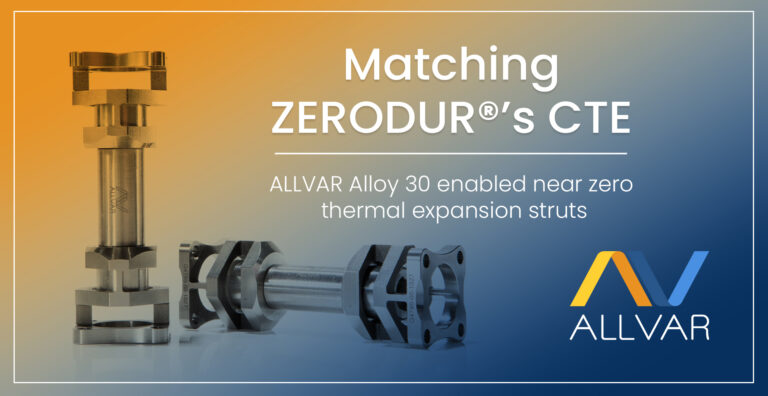
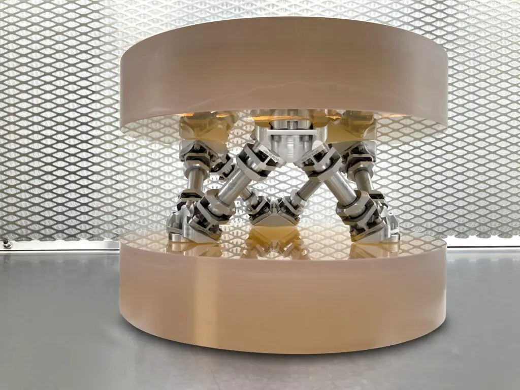
Today, we are discussing a real-world example where the CTE of multi-component struts was matched to the CTE of ZERODUR ® glass. By combining positive thermal expansion (PTE) metals and negative thermal expansion (NTE) ALLVAR Alloys a near zero CTE component was made. The struts were then combined into a hexapod structure support structure for a ZERODUR mirror resulting in an athermalized assembly.
In the previous blog post, Introductory Guide to Tailored Thermal Expansion, we discussed how ALLVAR Alloys can be combined with other materials to tune the effective Coefficient of Thermal Expansion (CTE) of a structure. This article expands on that idea.
This effort began back in 2018 as part of a NASA SBIR Phase II award titled, “Ultra-Stable ALLVAR Alloy Strut Development for Space Telescopes.” During the project, we successfully designed, fabricated, and tested a hexapod structure that matched the near zero thermal expansion (ZTE) of ZERODUR glass. The manufacturing methodology and basic strut design could be used to athermalize telescope structures that hold not only zero thermal expansion ZERODUR mirrors, but various types of mirror materials with different CTEs.
Ultra-low thermal expansion strut development background and requirements
From the onset, we had several high-level requirements for this project.
- The ALLVAR Alloy 30 struts needed a CTE near zero at room temperature for pm/√Hz measurements.
- The mirror assembly should demonstrate 100 pm/√Hz stability or better as required by the LISA Movable Optical Sub-Assembly (MOSA) stability requirement.
- The design needed to be suitable to survive launch loads.
- The individual struts and hexapod structure had to be designed for interferometric pm/√Hz testing.
The scope of expertise to achieve these high-level requirements required collaboration with experts in optical design, fabrication, and testing. ALLVAR partnered with Quartus Engineering and the University of Florida’s Institute for High Energy Physics to complete this project successfully. Quartus Engineering provided optic design expertise, component drawings, and telescope assembly services. The University of Florida Florida’s Institute for High Energy Physics provided guidance and testing for the pm/√Hz stability measurements using a Fabry-Perot interferometer setup currently being used to qualify the telescope prototypes for NASA’s LISA Mission.
Matched zero CTE strut design
In coordination with Quartus, we decided to use Titanium 6Al-4V, Invar, A286 stainless steel, and ALLVAR Alloy 30 for various strut components. Each material was selected for its specific material properties to provide the best overall performance. Invar was chosen as a bond-pad material because it is commonly used, it can structurally support mechanical fasteners, and its isotropic low thermal expansion properties reduces thermal expansion mismatch effects between the bond pad and the ZERODUR mirror. Titanium 6Al-4V was selected as a flexure material due to its strength, stiffness, and fatigue properties while A286 was selected as a screw material for its common use and high strength characteristics. The ALLVAR Alloy 30 would provide the NTE necessary to compensate for the PTE of each of these materials to get to a near zero CTE.
In order to test each strut using interferometry, the strut required a through hole so that an optical cavity could be created by attaching mirrors on each side (please see the figure below for details). As displayed, the Invar mounts were connected to the Titanium 6Al-4V flexures with four A286 screws while a large A286 screw held the Ti6Al-4V flexure to an internally threaded Alloy 30 tube. This configuration was mirrored on the other side of the strut.
To summarize, the strut that we would use to measure the overall CTE would consist of the following:
- 2 Invar mounts
- 2 Ti6Al-4V Flexures
- 2 A286 Bolts
- 2 Washers
- 1 ALLVAR Alloy 30 Tube
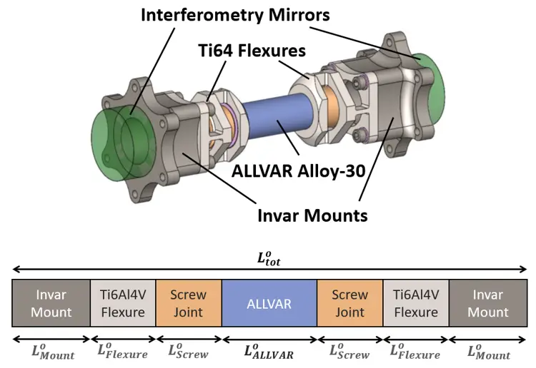
The CTE and relative length of each of the components contributes to the effective CTE of the strut. As the CTE values of each component and the overall length of the strut are fixed, we must determine the length of each component to produce an effective CTE that matches ZERODUR.
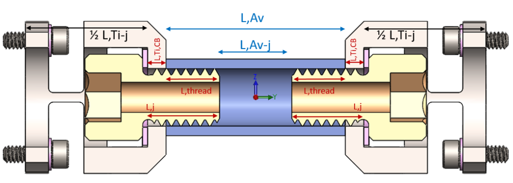
The above diagram shows the breakdown of the overall length into individual components. The diagram below displays a cross-section of the Ti6Al-4V flexures, A286 screws, and internally threaded Alloy 30 tube. The region where the threads of the A286 screw is engaged with the Alloy 30 creates an area with a CTE in-between the two materials. While this was estimated during the design phase, the actual value of the screw joint was not known.
To try and hit as close to ZTE as possible, we tested the CTE of each material and component in the target temperature range using push-rod dilatometry per ASTM E228 test method. Representative samples of Invar, Ti6Al-4V, ALLVAR Alloy 30, and A286 were evaluated. Additionally, a screw joint was fabricated and tested With the CTEs of each material and the screw joints measured, we moved onto determining final component dimensions to achieve and effective ZTE strut.
Using the terms in the above diagram plus adding a term for invar mounting blocks on each side, we can begin to determine the lengths of each component needed. Since ZERODUR’s CTE was the target, the lengths of the NTE ALLVAR Alloy 30 and PTE components were adjusted to tune the strut’s effective CTE to zero. The derivation of the equations is discussed below.
Equations for Tailoring Thermal Expansion
In this section, we will explore the equations used to tailor the thermal expansion of each strut. To begin, we must break down the strut into its individual components across its length. The basic equation for total length is shown below:
where:
- LTotal is the total length of the strut.
- LTi-j is the length of the Ti6Al-4V Flexure minus the section in parallel with the A286 screw.
- Lj is the length of the screw joint. In this case, the section where the thread engages with the Ti6Al-4V and ALLVAR Alloy 30 tube. This length was determined by the length of the screw we chose to use.
- LAV-j is the length of ALLVAR Alloy 30 not engaged with the screw joint.
- LI is the length of the invar mount.
With the formula for the total length, the change in length with temperatures can be determined by considering the changes in length, , due to thermal expansion. The equation for thermal displacement is as follows:
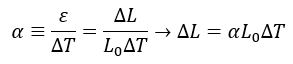
Considering the definition of CTE, α, and strain, ε , we get a relationship between CTE and this thermal displacement, , resulting from a discrete temperature change, ΔT , of a known length of material, ΔL :
Assuming uniform temperature along the strut length, the ∆T terms cancel each other and we are left with:
The thermal expansion coefficients of each component are known, the total length of the strut is known and a specific αTotal is desired. With 4 length variables between the Ti6Al4V, screw joint, Alloy 30 and Invar components, there are infinite solutions to achieve a desired αTotal . Therefore, the length of the screw joint was fixed by using the engineering rule of thumb requiring 5 threads be engaged while the length of the Invar mount was fixed based on the geometry of the bonding pad and angle of the final hexapod assembly. This leaves two variables, the lengths of the ALLVAR Alloy 30 or Ti6Al4V sections, which can be solved to match the CTE of ZERODUR. It should be noted that while we are trying to match the ZTE of ZERODUR for a specific hexapod geometry, different CTE values can be substituted for αTotal and different engineering principles can be used to fix the lengths of different components.
Determining the ALLVAR Alloy 30 Length for tailoring to ZERODUR®
First, we create an equation for the length of the Ti6Al-4V section that is not impacted by the joint by re-arranging the first equation we presented:
We can now substitute this equation into the equation for the effective linear thermal expansion of the total length of the strut:
Distributing the αTi term leaves us with the follow:
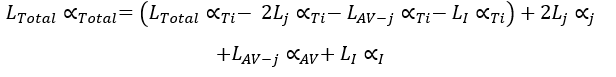
By combining like terms, we see the following equation:
We can now isolate the Terms related to the ALLVAR Alloy 30 section not engaged in the screw joint:
Finally, we divide both sides by (αAV–αTi )to isolate the term LAV-j :

All variables are fixed and known on the right-hand side of the equation. To determine the total length of the ALLVAR Alloy 30 tube, the lengths of the two screw joints must be included. Therefore, the length of the ALLVAR Alloy 30 tube can be calculated by:
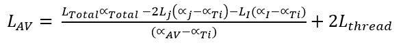
where Lthread is defined in the figure of the strut cross-section above.
Determining the flexure length to tune to near zero CTE
We can return to the equation we used earlier to determine the Length of the Ti6Al-4V section minus the joint:
To determine the total length of the Ti6Al-4V flexures, we take the section of Ti6Al4V without the screw joint and add the lengths of Ti6Al-4V in each threaded joint section (indicated as L,Ti,CB) above.
We can divide that number in two to get the length of each Ti6Al-4V flexure.
With multiple components and varying materials, we are able to determine the lengths needed of both positive and negative thermal expansion components to tailor the thermal expansion to a specific value. We chose a near zero CTE for this multi-component strut, but this methodology can be applied to any thermal expansion value between the highest magnitude negative thermal expansion and the -30ppm/°C CTE of ALLVAR Alloy 30.
Results
After interferometric testing of both the individual struts the average thermal expansion between all six struts was 0.66 ppm/°C while the standard deviation was 0.05 ppm/°C. The average CTE value is within the uncertainty of the material CTE values determined via pushrod dilatometry. Interestingly, the strut’s very low CTE standard deviation was achieved with standard machining tolerances of +/- 0.025 mm. We believe with better material CTE metrology and an iterative manufacturing process to the struts could be made to match ZERODUR’s® CTE even better and achieve a zero CTE.
As for the pm-level stability tests, a stability of 2 pm/√Hz was achieved for the individual struts and a stability on the order of 11 pm/√Hz was achieved for the full hexapod assembly. This stability is an order of magnitude better than the 100 pm/√Hz success criteria originally proposed.
If you are interested in learning more about this project, please check out the Quartus Engineering and ALLVAR webinar covering this project.
Don’t forget to follow ALLVAR on our LinkedIn page, check out our YouTube page, and subscribe to our newsletter to stay up
to date with our latest news and events! As a team of passionate material scientists and engineers, we would love to connect and answer any questions you may have about our revolutionary material.